Berik Visschers
A log of repairs and creations
Repairs
- Music unscrewed
- Friendly repair for a friend
- Osqar shines bright
- Blown capacitor
- Sugden A25 - Professional Repair
- Sony DD Walkman: Broken Main Gear Replacement
- THE BILLIARD COMPUTER IS BACK ONLINE!
- Computer Speaker Jack Replacement
- Under Pressure: Breathing Life into a Medical Device
- Stuck in Spin: Reviving a Jammed DVD Tray
Friendly repair for a friend
Repair for a friend
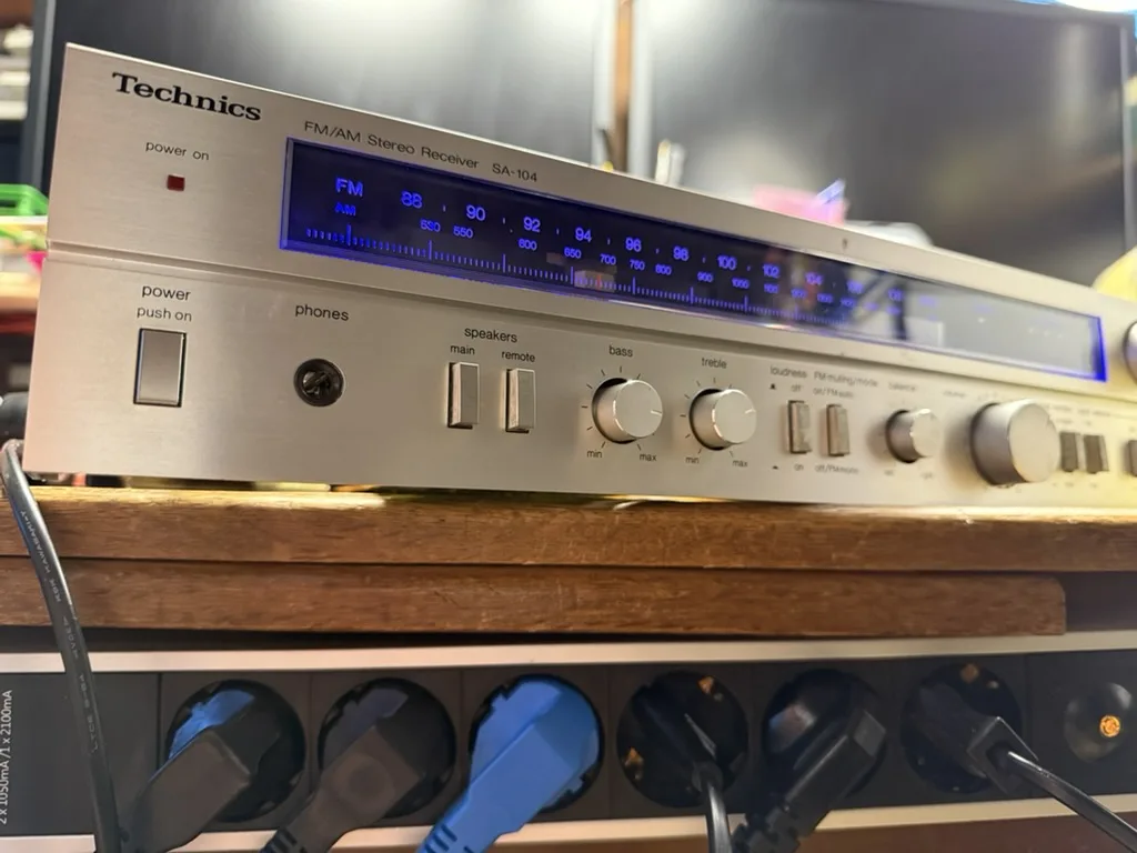
These are the innards of the Technics Model No. SA-104.
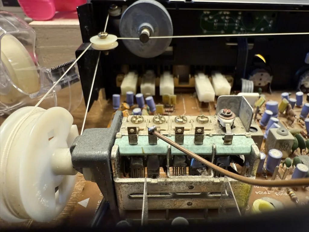
The radio dial wire is guided throughout the machine — quite spectacular. In the front here is the tuning variable capacitor. In the back, you see the flywheel connected to the button shaft, giving the tuning dial that extra quality feel.
When we started, the amplifier didn’t do anything. My friend had previously replaced some transistors that are part of the power supply section, as well as a power resistor that had burned out. This was some time ago, and the repair had stopped there.
Now we have a look at this amplifier together and hope to get it back to operational.
Safety first: I trace the line voltage leads. The PCB that receives the line voltage needs to be unscrewed and put aside to gain access to the power supply section below. I wrap this PCB in a plastic bag and tape it shut. We still need to be careful with mains voltage, but the biggest risk is now one layer of plastic away.
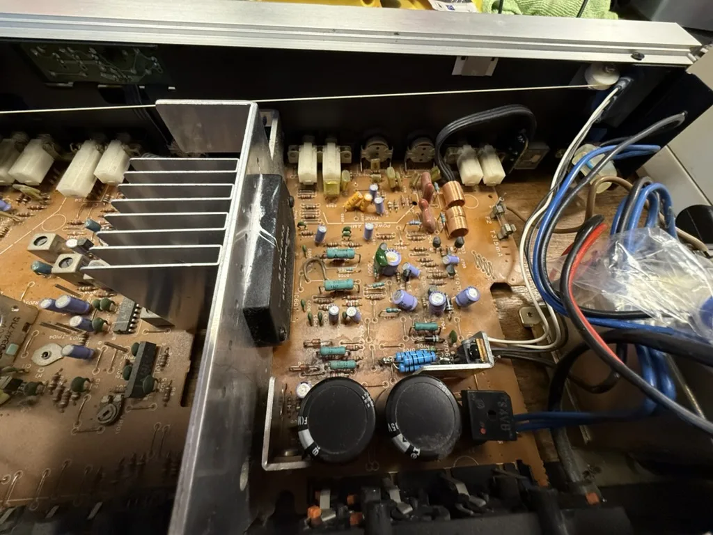
We plug in the amplifier and measure the voltage coming out of the transformer. There is a -32V AC and +32V AC rail, both stable.
Next, I measure the DC rails after the rectifier (the black square at the lower right). These rails can be easily found — the two capacitors (big black circles at the bottom) are connected to them, one for each voltage rail. I measure these from the bottom side of the machine.
Luckily, the bottom plate of the machine can be removed. Vintage machines often have features that make them easier to repair, like better access.
I measured both capacitors — first resistance, then farads. The negative rail capacitor measured 4200µF, while it should be 4700µF. This is below its specification, but not enough for the amplifier to stop working. The other measured 4800µF — no problem.
I find another, much smaller capacitor that looks like it has experienced some internal pressure. Aluminum electrolytic capacitors (the ones that often look a bit like batteries) can start to boil and push up the top. Some even have grooves in the top of the housing so that overpressure is released more predictably and visibly. Measuring capacitors in-circuit doesn’t always work. In this case, I remove the capacitor to get a proper reading. It reads fine. My friend suggests replacing it, but I’d like to first find the fault before replacing anything preemptively.
This is the point where studying the circuit is required. Luckily, the full circuit diagram is documented online.
Studying closely, we find some failed solder joints. Next time I find a broken solder joint, I’ll make some good photos to show you. But broken joints are hard to spot anyway: the solder is like a mirror, and the crack is often just a very thin black line. Now imagine such a small feature between all the lines and shiny dots of a big PCB, and you’ll understand how easy it is to miss. I found the dry solder joint by wiggling components in the power supply section of the PCB. One of the rectifier diodes felt “swampy”, sticking to whichever side you push it. Components should feel springy when pushed — that was a clear indication.
My friend found two 4700µF 35V replacement capacitors, and we replaced both original rectifier capacitors. I touched up the failed solder joints and double-checked some of the previous work.
Next, we powered up the machine, and the power supply had both negative and positive rails working.
However, the display lamps didn’t work, and we had no good way to test the audio.
First, the display lamp. We removed the lamps and found both were broken. My friend selected a blue and a white LED to replace the original 12V lamps.
We need a resistor to drop the 12V to something the LEDs will accept. I estimate roughly that an LED will take 2V, so we need to drop 10V at roughly 20mA.
The formula we need here is:
U = I × R (Voltage equals current times resistance)
We need to find the resistance, so we rearrange the formula:
R = U / I = 10V / 20mA = 500 ohms
We pick 470-ohm resistors and mount the LEDs where the glow lamps used to be. We test the preamplifier with a set of headphones and confirm that it works — both the radio and the Phono, Tape, and Aux inputs.