Berik Visschers
A log of repairs and creations
Repairs
- Music unscrewed
- Friendly repair for a friend
- Osqar shines bright
- Blown capacitor
- Sugden A25 - Professional Repair
- Sony DD Walkman: Broken Main Gear Replacement
- THE BILLIARD COMPUTER IS BACK ONLINE!
- Computer Speaker Jack Replacement
- Under Pressure: Breathing Life into a Medical Device
- Stuck in Spin: Reviving a Jammed DVD Tray
Sugden A25 - Professional Repair
Professional Repair
A repairman asked me to repair his Sugden A25 amplifier. What an honour!
The machine works, but there is an audible 50Hz tone coming from the speakers. I immediately conclude that this must be the rectifier capacitors.
After receiving the machine and opening it up, there is a clear visual confirmation:
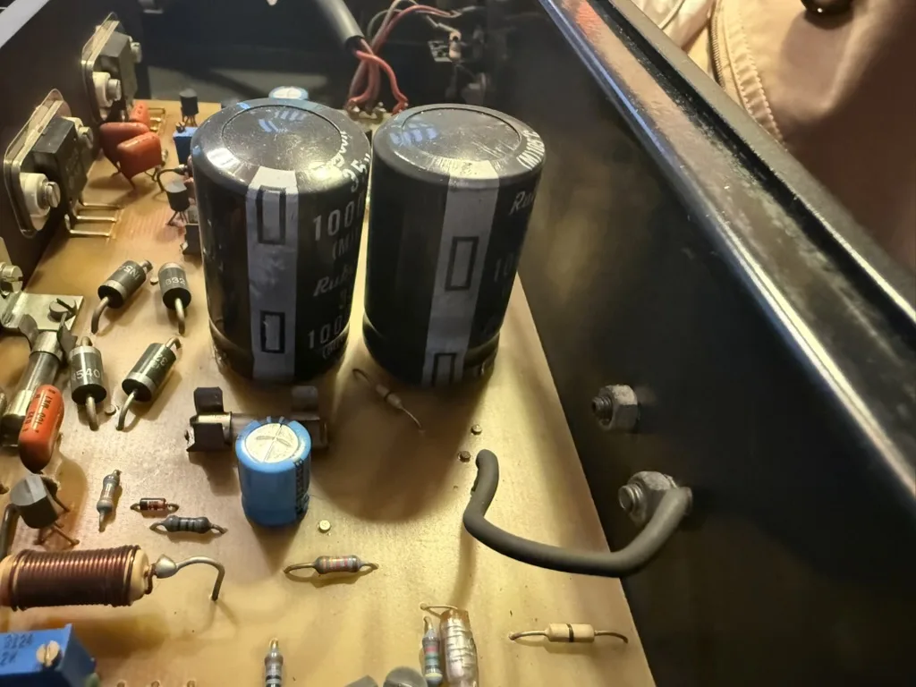
Both capacitors have formed a slight bulge due to internal pressure buildup.
I remove both, and they measure 1000x less than their rated value. Due to the way they are laid out on the PCB, and the height of the machine, I need to order the exact size: 35mm by 20mm, 10mm lead spacing. These are Rubycon branded capacitors — Sugden did select quality components! I can only order a batch of 500 Rubycons of the correct value and size. I check in with the customer to see if they mind another brand. I get a reply of full confidence in my expertise and go ahead with the repair.
Let’s be diligent, now that I’ve received full confidence. I inspect each component on the PCB and see some interesting features.
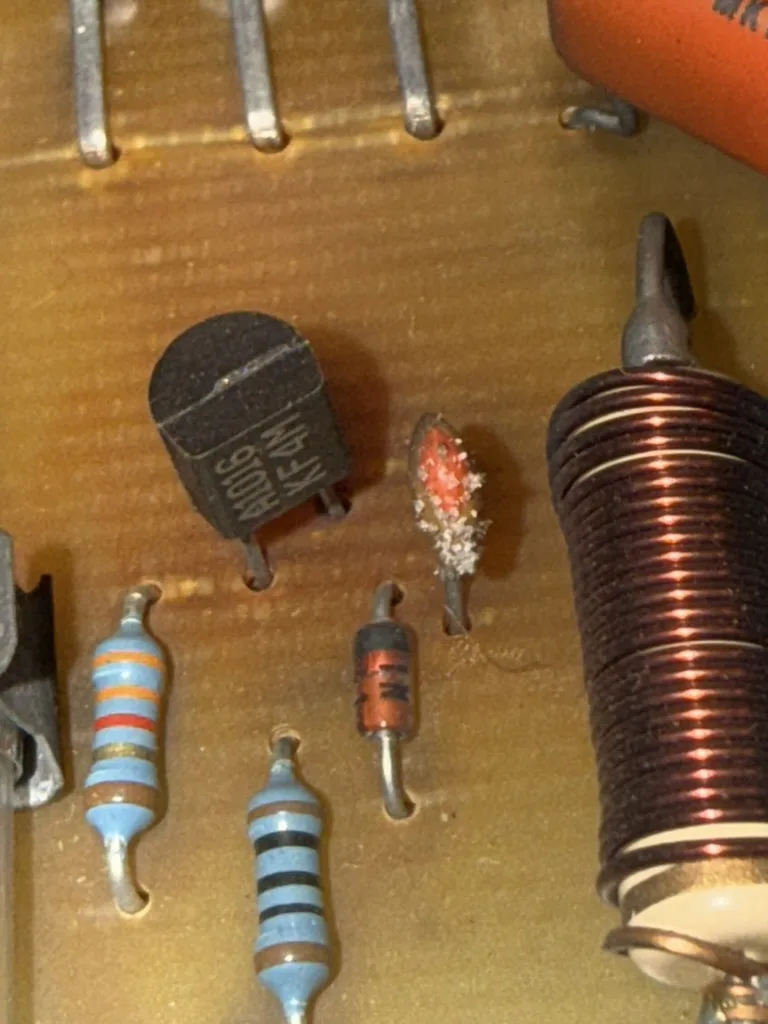
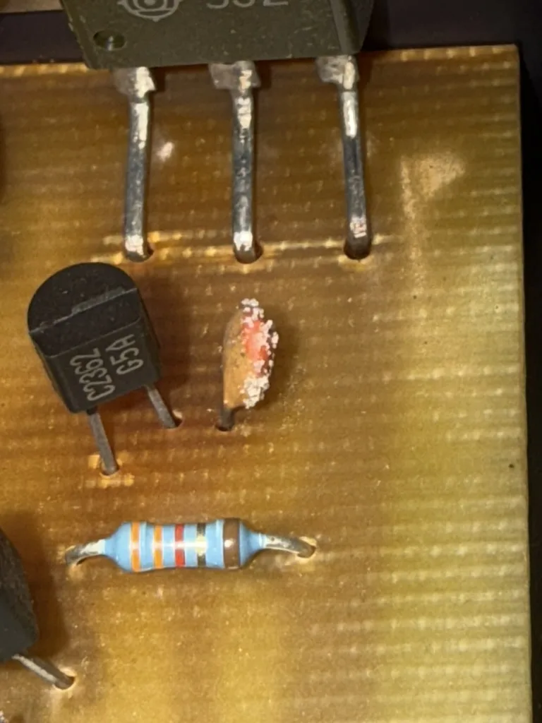
Three things to notice here:
- The PCB seems to have been bent along the power transistor legs
- The PCB shows some slight discoloration around the transistors
- The ceramic capacitors have developed a white, stubbly beard
I first deal with the capacitors. For each type, I desolder one or two and measure their value out of circuit. Quite a few capacitors are out of spec:
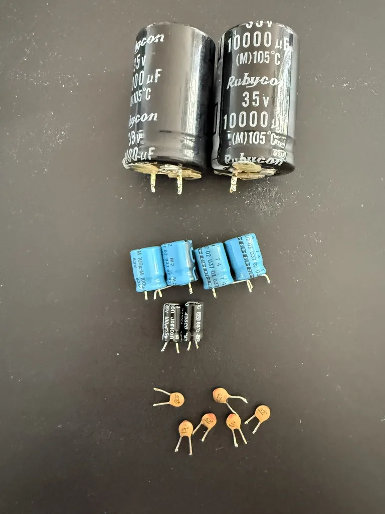
The two big ones are the rectifier capacitors that failed completely. The others still have some value, but less than specified (whatever it says on the outside ±20%, for most capacitors). Also, ideally, if there are four capacitors with the same specified value, you wouldn’t want to see one being +20% and another being -20%.
I leave the capacitors that measure fine — they’ve survived over 40 years, and chances are good they’ll survive another 40. For the out-of-spec capacitors in the photo, I order replacements.
The PCB bend marks are not visible on the side with the traces, nothing to worry about. There is quite some 40 year old flux residue on the solder side of the PCB, which I clean up using some isapropanol alcohol.
There isn’t much point in testing the amplifier without having good capacitors in place. Instead, I do some work on the front panel.
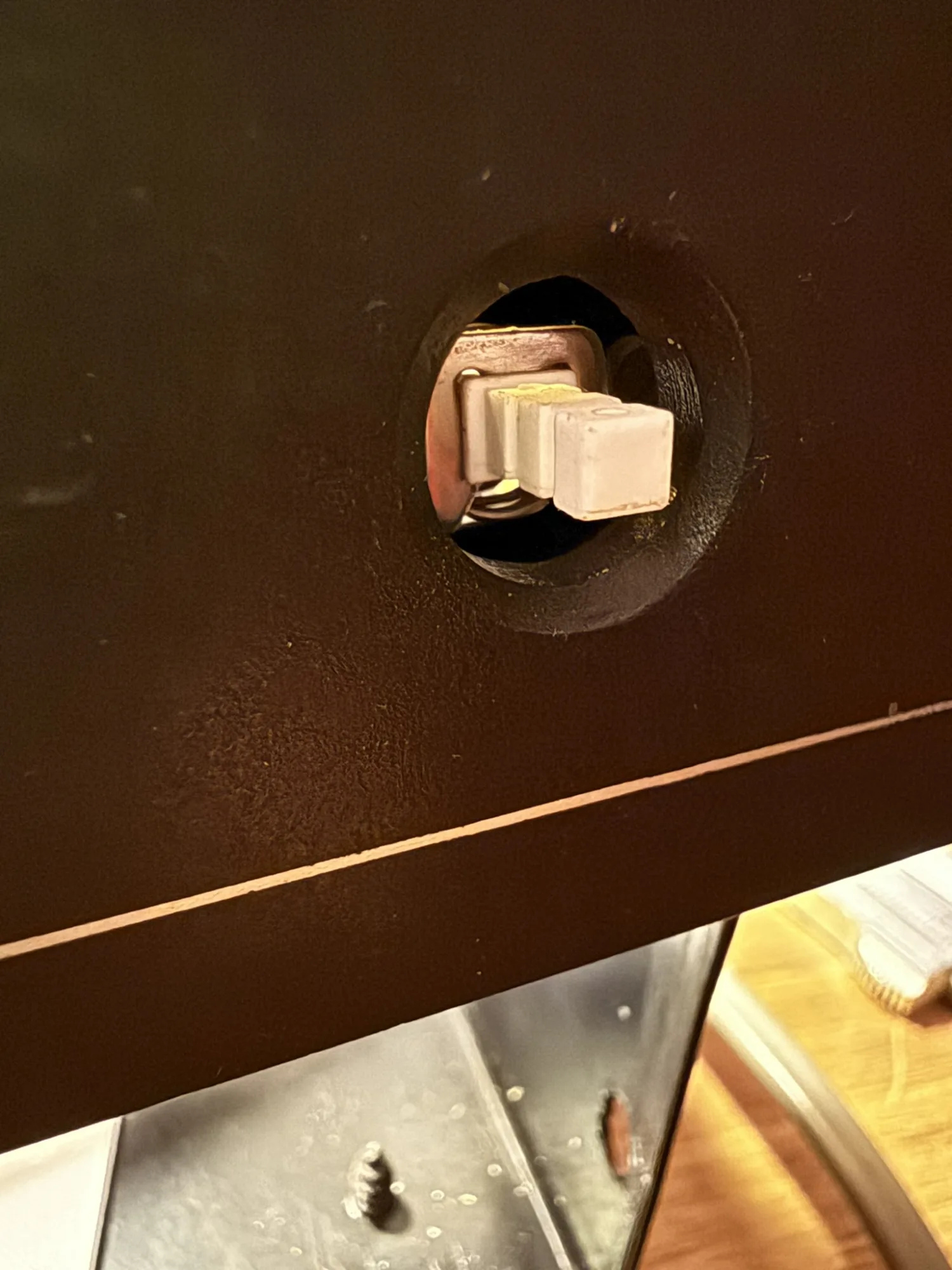
One of the knobs is missing, and another is split in two.
I ask a friend with a 3D printer if they fancy printing a knob.
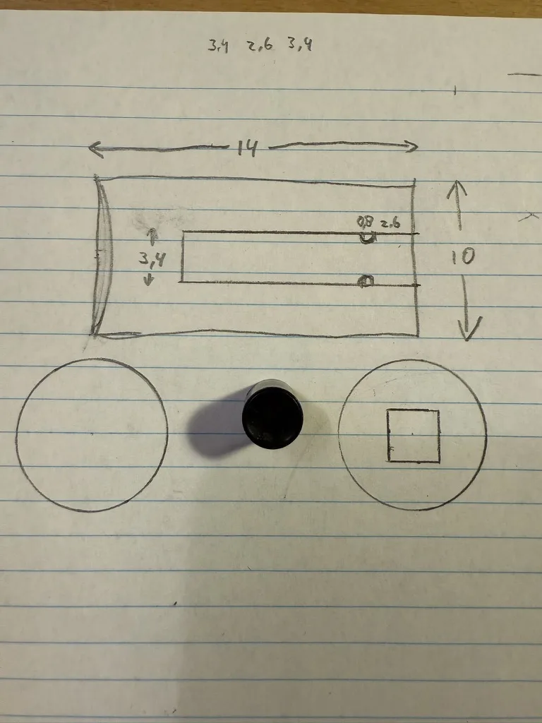
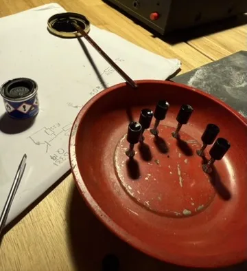
I measure and sketch the knob specifications, then visit my friend with this piece of paper. About an hour later, we have the first attempt printed.
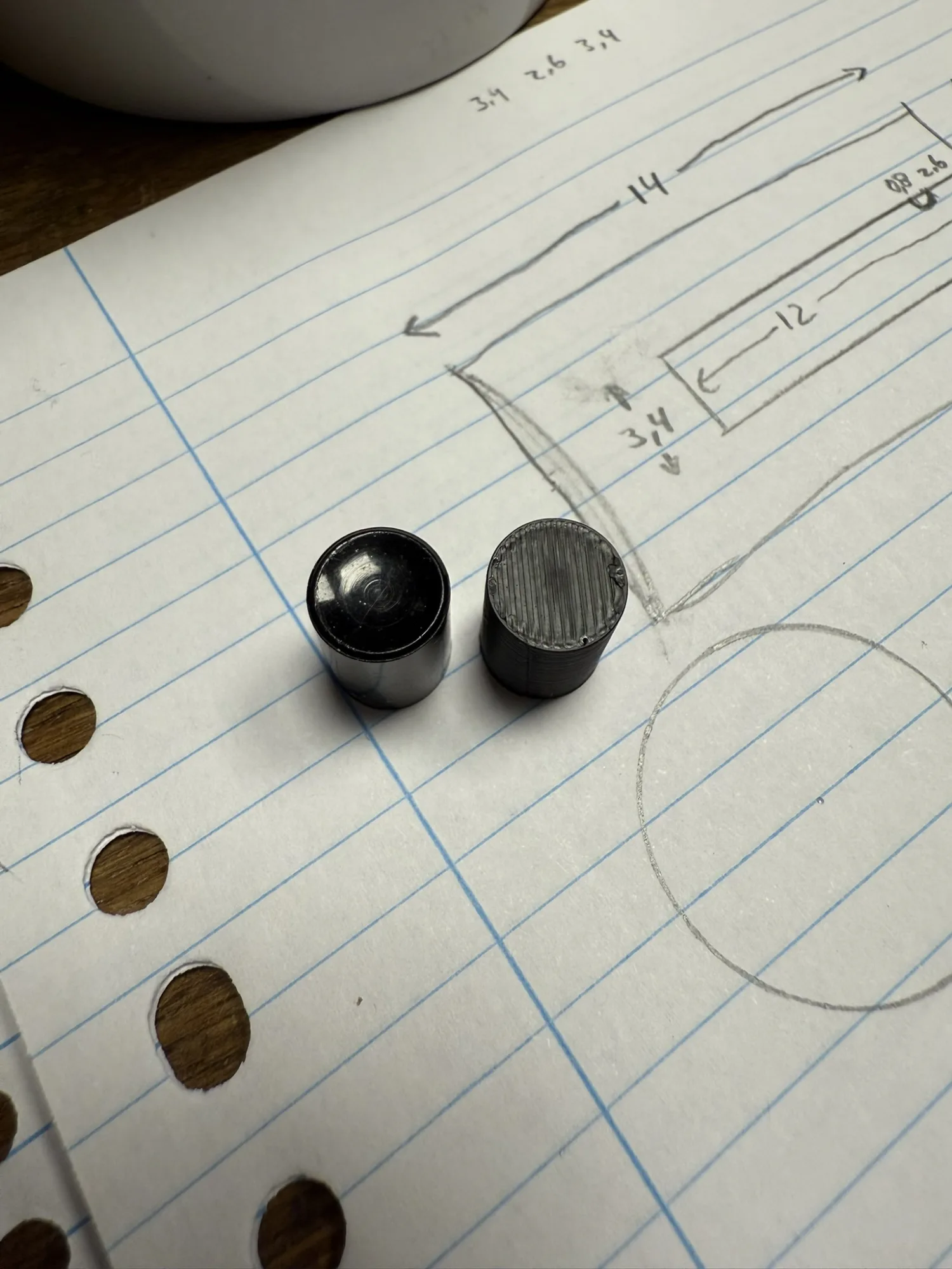
In the photo above, the original knob is on the left, and the printed knob is on the right. I ask my friend if the inset can be printed as well. The next day, they deliver:
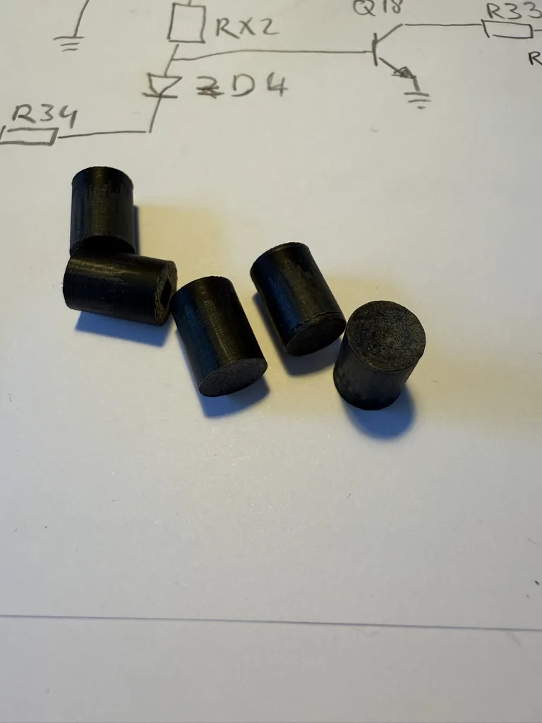
I spend 10 minutes per knob flattening the print lines, then sanding, then painting.
One gets a different treatment. Being printed in red, I add a few layers of red spray paint with a nice gloss.
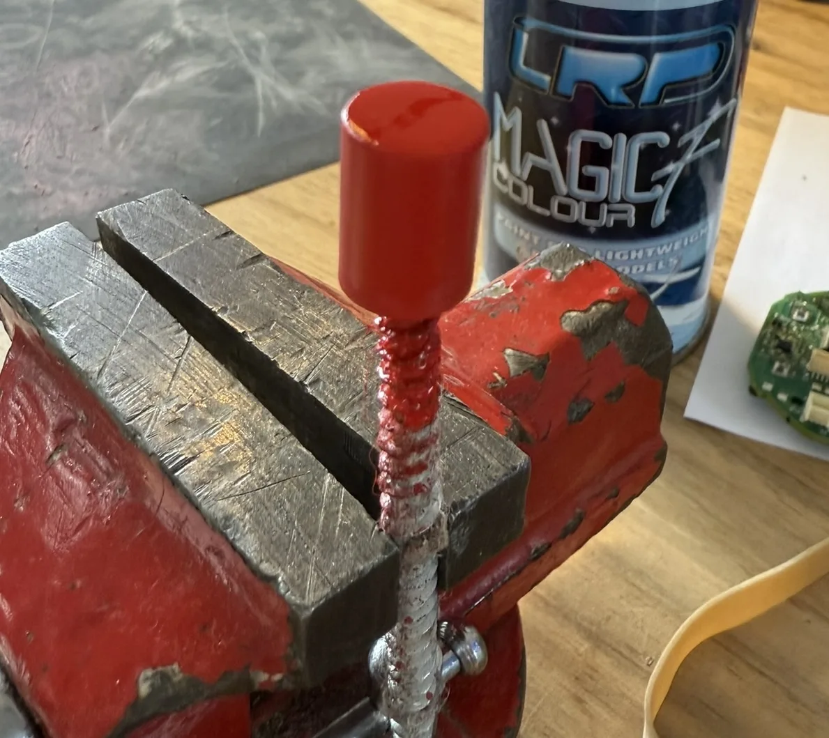
I’m proud of the result:
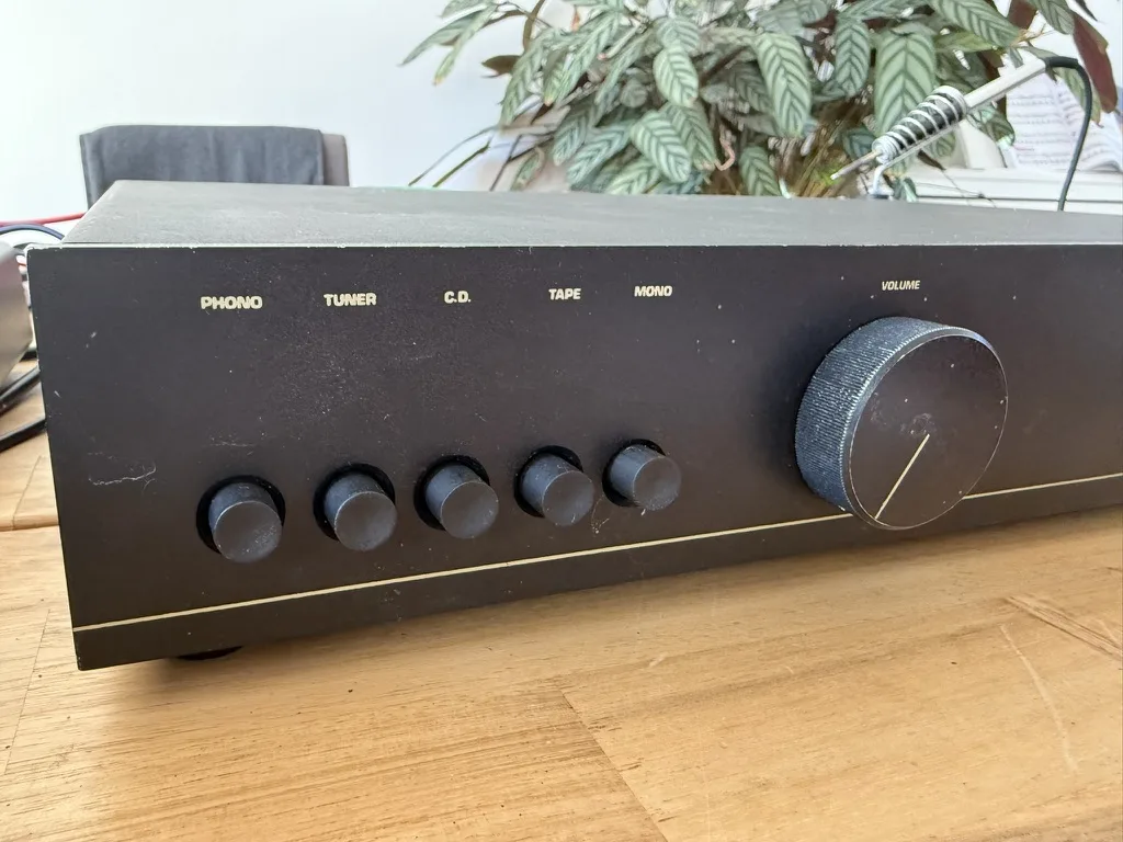
I fix the knobs in place with some silicone glue. This type of glue does not become fully hard, therefore the buttons can be replaced later if needed.
I show the result to the customer: “A red button?!” he responds jokingly. I tell him he’ll receive an extra black button and can decide which one to use himself.
Once the capacitors arrive by mail, I continue with the electrical repair. With the new capacitors in place, I test the amplifier. The 50Hz hum is gone. The volume knob crackles when turned. Otherwise, the amplifier works as expected.
I fix the volume knob using some contact spray. I spray a bit of contact spray through the small gaps of the potentiometer housing — on the Sugden that’s the blue box right behind the volume knob — then rotate the volume knob up and down for a minute or two.
Time to go the extra mile. I check the documentation for the bias current and find it should be between 80 and 100 mA. To measure the bias current, remove one of the four fuses near the power MOSFETs and replace it with a multimeter in current measurement mode.
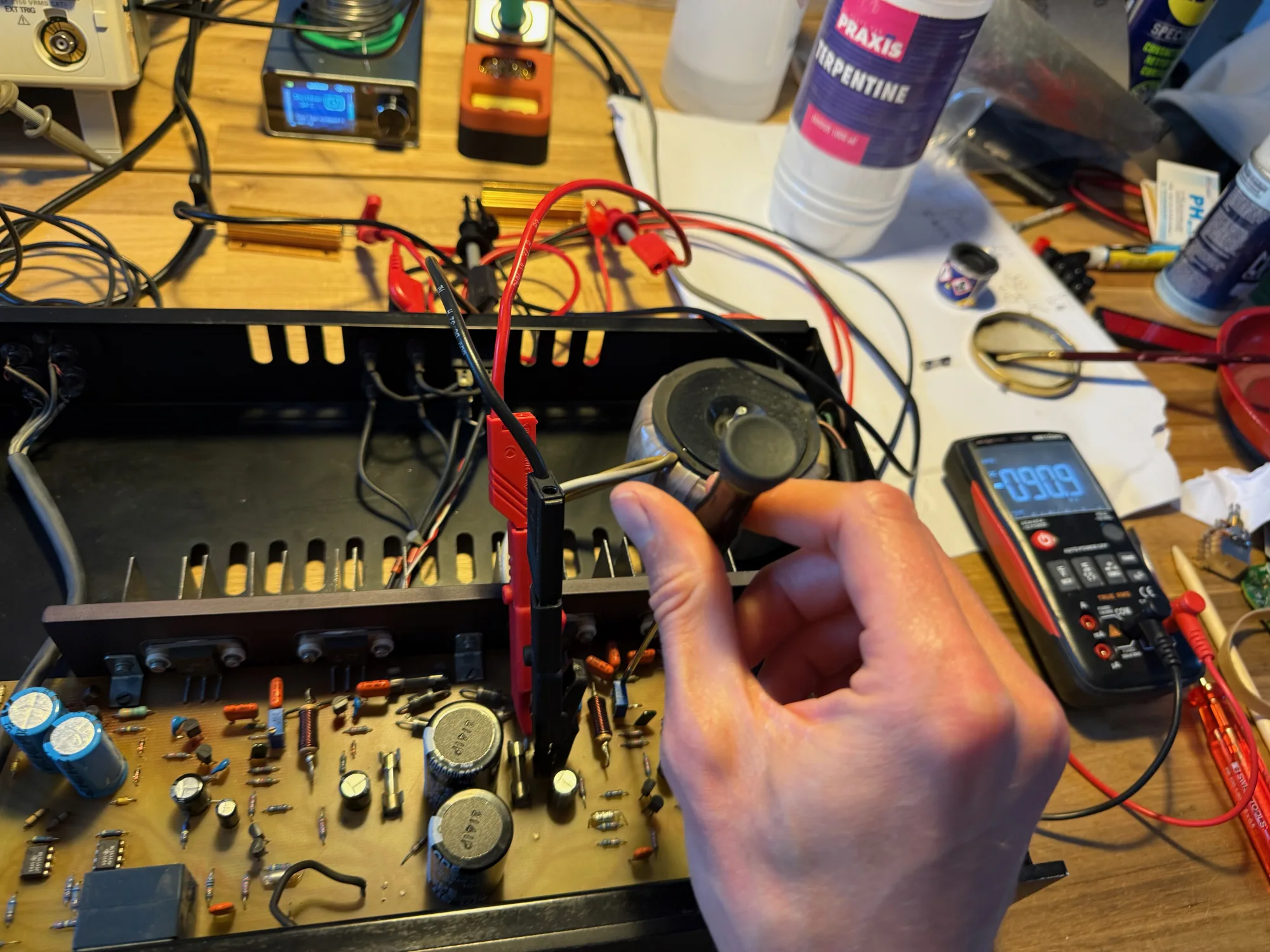
The Sugden measures around 110 mA on either channel. I tweak both trimmer pots to set the bias current to 90 mA. Then I wire the input and output of the Sugden to an oscilloscope and check how well the output matches the input when feeding a 5 kHz sine wave. The scope trace looks excellent — repair done!
Lastly, I apply some silicone glue to the bigger electrolytic capacitors. This amplifier won’t be shaken much, but I want to deliver quality. A bit of silicone glue relieves the stress on the capacitor leads when the amplifier is moved or shaken.
When the customer comes to pick up their amplifier he tells me that the amplifier has been turned on for most of its life. This explains the rectifier capacitor issue perfectly. These rectifier capacitors have been maintaining a voltage for 40 years, they’ve held up well: The replacement capacitors have something to live up to.