Berik's blog
A log of repairs and creations
Repairs
- Music unscrewed
- Friendly repair for a friend
- Osqar shines bright
- Sugden A25 - Professional Repair
- Sony DD Walkman: Broken Main Gear Replacement
- THE BILLIARD COMPUTER IS BACK ONLINE!
- Computer Speaker Jack Replacement
- Under Pressure: Breathing Life into a Medical Device
- Stuck in Spin: Reviving a Jammed DVD Tray
THE BILLIARD COMPUTER IS BACK ONLINE!
Repair Café De Bieb, Utrecht
The repair day is nearing its end, I had a lot of fun repairing a medical device. What more can one ask for?
I roam around to see what repairs are in progress on the other tables when I get called over for a micro USB replacement job.
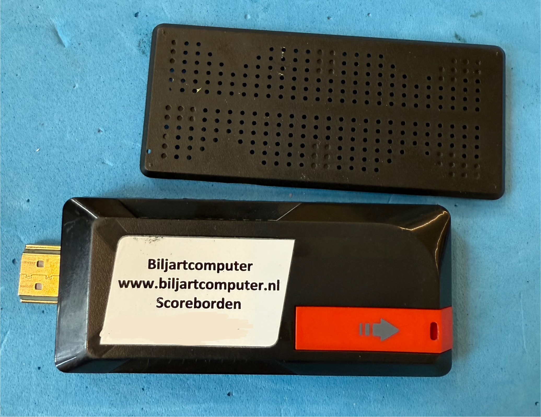
The customer shows me this device:

What. Is. That?
“A computer, for playing billiards”, the customer explains.
There is an HDMI plug sticking out of the device. This must be similar to a Chromecast, but instead of displaying YouTube commercials, it tracks and shares your billiard scores! I guess there is a community, challenging each other for competitions. Meeting IRL, and using these devices to share their match outcomes.
A whole world I didn’t even know exists!
On to the repair. The micro USB port that powers the device has ripped off.
That is not uncommon for USB powered devices.
One of the repairmen on De Bieb specializes in USB port replacments, they’ll fix one in under 10 minutes. This is my first USB port replacement..
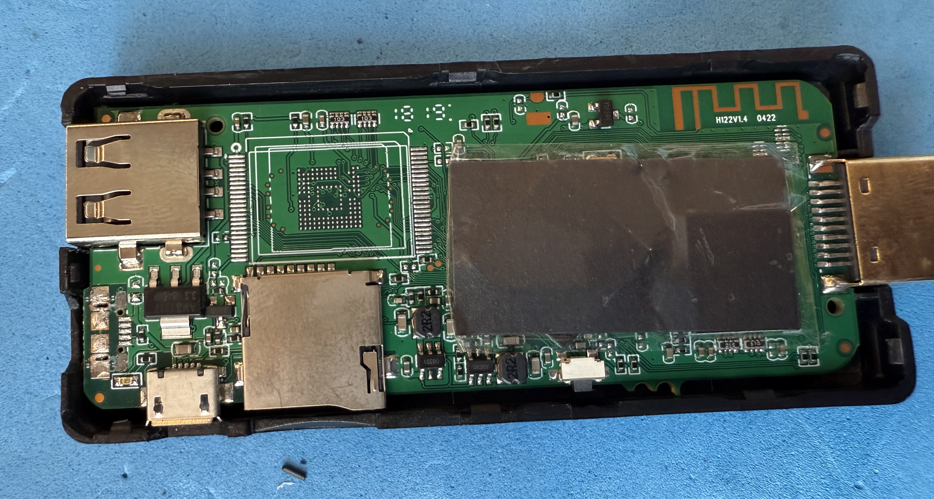
Let’s peek inside:

Next to the ripped off conector, we see a voltage regulator, a USB-A port and another micro USB port. Underneeth the heat conducting tape is a CPU and HDMI driver IC. On the center bottom is a micro-SD card holder. Here is where your scores will be stored off-line.
A WI-FI or bluetooth antenna can be seen snaking up and down, in the top right corner.
A detail of the place where micro USB port used to be:

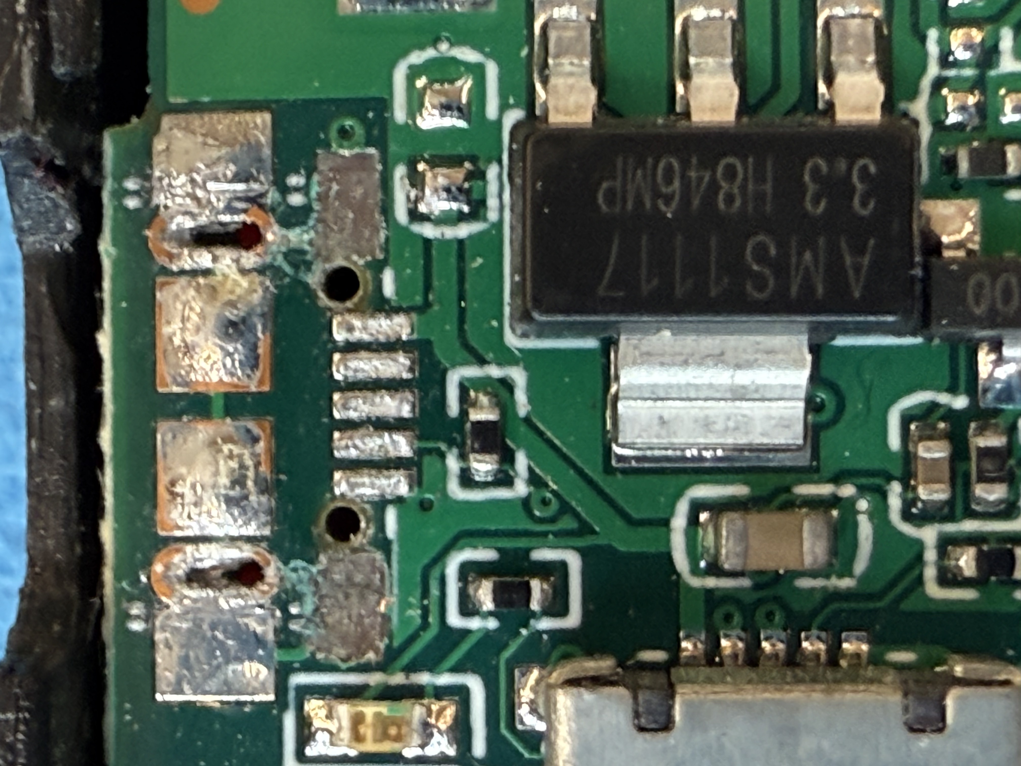
The pads that held the USB port in place have been pulled off. Other than that, the damage is minimal. I tell the customer that this repair will succeed. They react a bit sceptical.
The five pads that look like a cross-walk (“zebra-path” in Dutch, such a great word) are “the USB pins” while the shiny silver looking pads on top are connected to the “USB shield”.
To get a sense of scale, the zebra-path width is roughly 3mm. My iron tip is 2.4mm wide.
The two pads that have been ripped off used to connect to the USB shield. The fact that only these pads were ripped off tells us that the original USB port was not soldered properly. It should have been soldered to the pads above, but it wasn’t.
This USB port is for powering the device, the power is delivered over the two outermost zebra-path pads. The second-from-the-left pad is also needed, the resistor below the zebra-path tells a charger that a power hungry device is present. The last two pads are the data lines (up and down), and are not connected to anything on the PCB, in this case.
This specific micro USB connector is a bit special: The two mounting pins are a little closer together than normal. The mounting pins fit into the oval holes in the PCB. A regular micro USB port will have them to the side of the port. This port has them tucked underneeth, which makes soldering much much harder.
Luckily repair café De Bieb has these less-common parts on stock.
I need to take care of two things:
- The new micro USB port is properly affixed to the PCB
- The new micro USB port has the five zebra path pads connected to its leads
I could have, and maybe should have, used the hot air soldering station.
I didn’t. The soldering station has to be found and set up. My regular soldering iron was ready for use. Also, there are other ports and tiny components just near to the ripped off port. Heating up the whole area risks loosing them.
I push on, using my regular iron. Lets do this!
This is how I replaced the micro USB port
I use a D24 (spade shaped) tip on my T12 iron. I find this size ideal. It manages well on pretty big amounts of copper. And with some finesse, you can work on 0.2mm features like these.
- Clear the solder from the PCB using flux, a tin sucker and wick
-
Solder the matching micro USB port side lugs to the PCB
Carefull here. I had some solder entering the USB port. To get it out:
- Push a USB plug as far as possible into the port, pushing the tin aside, and take the plug out again.
- Heat the port until the solder inside melts
- Repeat
After three times, the connector fully fit into the port. Extra snug.
Next time I’ll use less solder.
-
Solder the USB port pins
Using the spade style soldering tip:
- Add flux. Add enough flux. Flux makes difficult soldering jobs doable
- Make sure a tiny layer of tin sticks to the tip of the iron
- Get the amount of tin right, use flux to keep the tin fluid
-
Now, with the tinned side of the tip facing downward, press the USB pins down onto the PCB pads
The iron tip is much bigger than the pins and pads. No worries though, if you use flux, the tin will creap between the metal parts and clear the places where it shouldn’t be. Do not add tin directly, add flux intsead.
- Press down for 2-3 seconds until a nice sizzle starts
- Now pull the iron tip away from the pads and port
- Let the area cool a bit, then repeat until it looks decent
I did manage to touch the voltage regulator with the soldering iron (see below).
-
Lastly, Use isopropyl alcohol (IPA) with Q-tips to clean the flux from the PCB and port
Some types of flux will damage the PCB traces and components over time, if it is left uncleaned
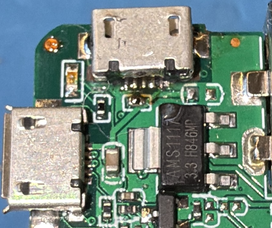
The new port soldered:

Once the device is assembled, we walk to a presentation display and plug the biljartcomputer into the HDMI port; then plug a USB adapter in the repaired USB connector. We see the boot screen of biljartcomputer.nl
THE BILLIARD COMPUTER IS BACK ONLINE!
We don’t have a billiard table nearby, would have been nice to see the device in action!
Soldering advice
The parts that need to be soldered should be at least 250 degrees C, for at least half a second.
This means you press the iron tip onto the joint. Wait until everything is hot. Keep it at that temperature for a second or two. Then remove the tip while not moving the components. Wait for the parts to cool down before trying again.
Do not stroke components with the soldering iron. Do not try to knead the tin into place.
In. Wait. Out. Wait.
Trust that the tin will flow between the metal and away from clearances.
In case the joint is not good, repeat from the beginning. Do not press on when things go sideways.