Berik Visschers
A log of repairs and creations
Repairs
- Music unscrewed
- Friendly repair for a friend
- Osqar shines bright
- Blown capacitor
- Sugden A25 - Professional Repair
- Sony DD Walkman: Broken Main Gear Replacement
- THE BILLIARD COMPUTER IS BACK ONLINE!
- Computer Speaker Jack Replacement
- Under Pressure: Breathing Life into a Medical Device
- Stuck in Spin: Reviving a Jammed DVD Tray
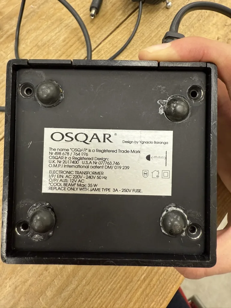
Osqar shines bright
De Reparatiebalie
This is Osqar,
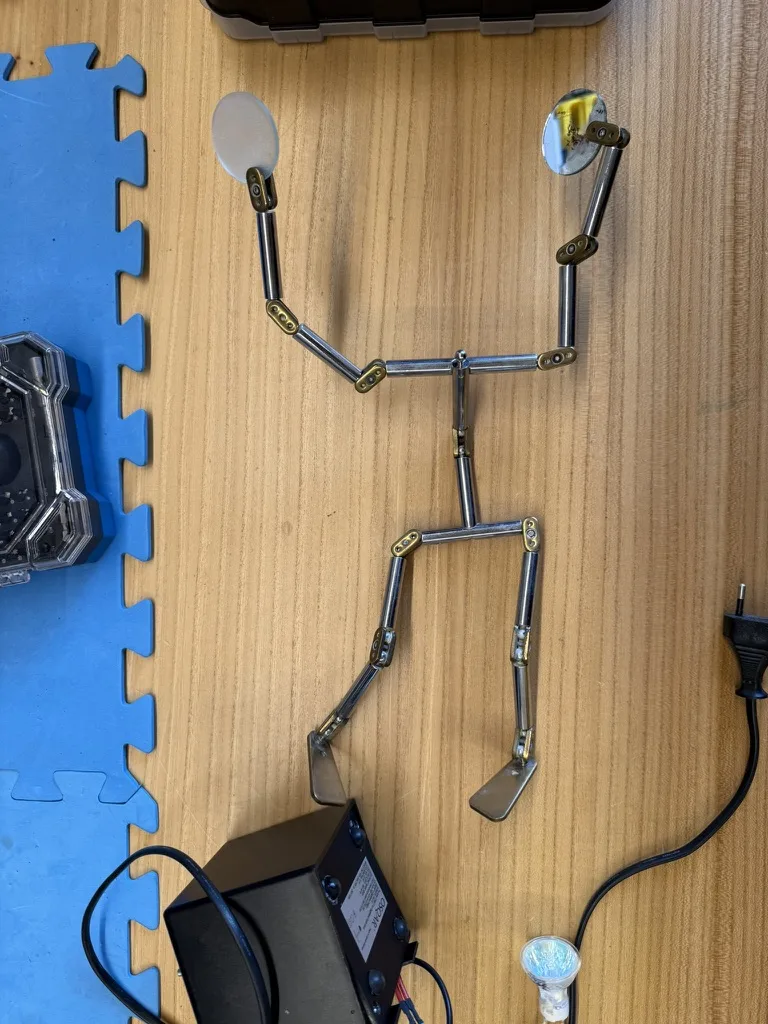
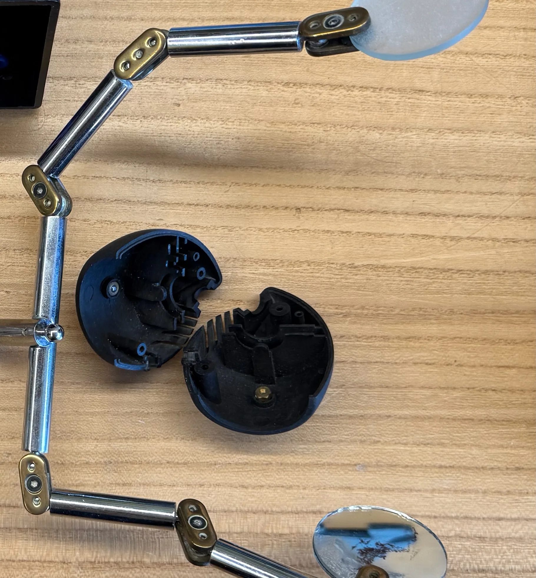
Osqar can’t shine anymore.
His head split in two.
And his power supply stopped working.
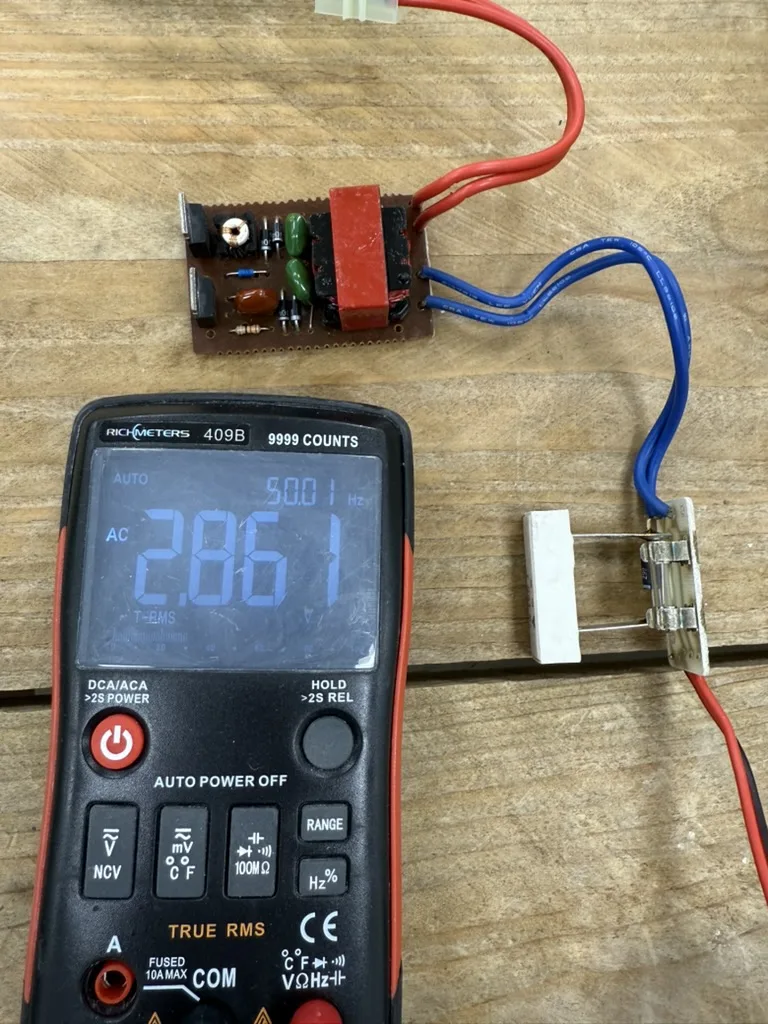
The output shows a mere 2.8V AC, where we would expect 12V.
Let’s deep dive into the design of this 12V power supply.
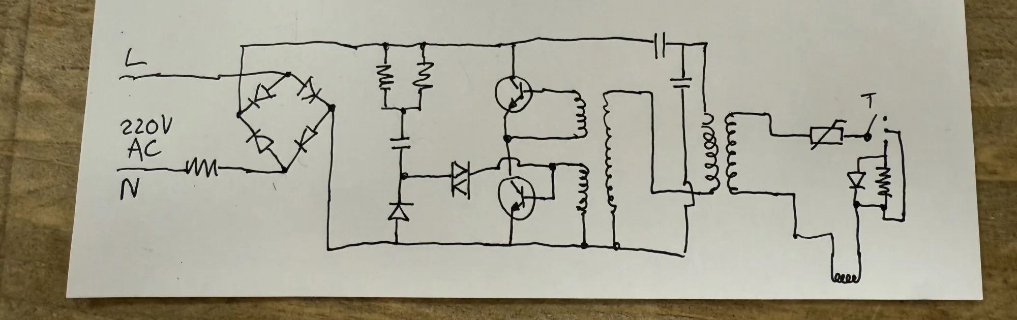
This is its circuit diagram:
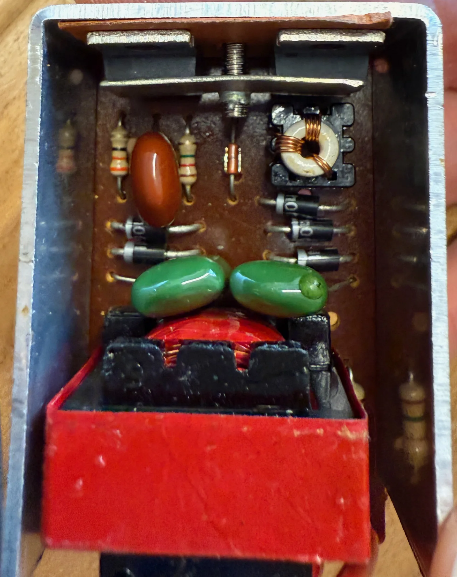
On the left we start with the 200V AC input, which first goes through a Fusable Resistor and then enters a Full Bridge Rectifier.
From here we enter a region of black magic. This region lasts all the way until the transformer – the two whirlpools facing eachother near the right edge of the circuit. Lets skip this section for now and concentrate on what comes after the transformer.
After the transformer, the voltage level is 12V AC. This low voltage section of the circuit has a separate PCB. It includes a fuse; a switch to select either off, low or high (the component with a T above it, the T represents a button, it isn’t drawn perfectly clear here); and a resistor and switching diode to turn down the light in the low mode; lastly the lamp is on the right bottom of the circuit, represented with another whirepool like curve, facing down.
Interestingly, the high / low selection does not save any power in the low mode. Instead it warms up a big resistor to reduce the lamp brightness. This resistor is a 5W one, it is the white rectangular component next to the multimeter in the photo above.
Now for the center part of the circuit. Lets start at the transformer on the right. Transformers can be made smaller and more efficient by increasing the frequency they work at. The power company in europe delivers 50Hz, which is quite a low frequency. You’ve heard the tone before, it is part of the sound that a vacuum cleaner or kitchen applience makes, some power adapters produce a soft 50Hz hum, and near power lines you often hear the static fibrate with this low frequency. 50Hz, it turns out, requires big and inefficient transformers. To solve this inefficiency, this circuit runs the transformer at a much higher frequency. To produce the higher frequency, first the 50Hz is rectified and made into 325V DC (230V AC equals 650Vp-p, which gives 325V rectified). The center of the circuit contains two power transistors configured such that they will start oscillating, driving the transform at a predictable high frequency.
This type of power supply is called a switch mode power supply (SMPS). There are many variants of SPMSs, this is an early version. Modern SMPSs designs look very different. They are based on one or more power MOSFETs and a dedicated chip for driving them.
On to the repair. I test each component one by one and find no issues. Bummer.
It took me way longer to find that the transformer had failed than I want to admid. Transformers are hard to measure with a multimeter. When you measure their resistance, most will read close to zero ohms. If a transformer is shorted internally, it will also read very close to zero ohms. See the problem? I first unsoldered the transformer and then convinced myself that the transformer resistance on the 325V side was too low, being below 1ohms. The high voltage side of a transformer should read a higher resistance than the low voltage side. A value below 1ohms only makes sense for a really powerful transformer or a very low voltage transformer side. In this case its neither.
Replacing the transformer will be difficult. There tranformer did not come with any specification or product number.
Time for plan B.
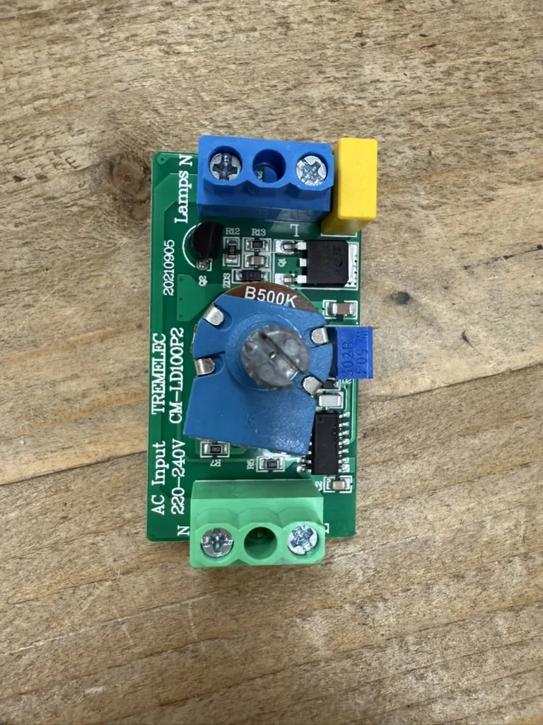
I found a generic dimmable 12V adapter, and a 220V dimmer board.
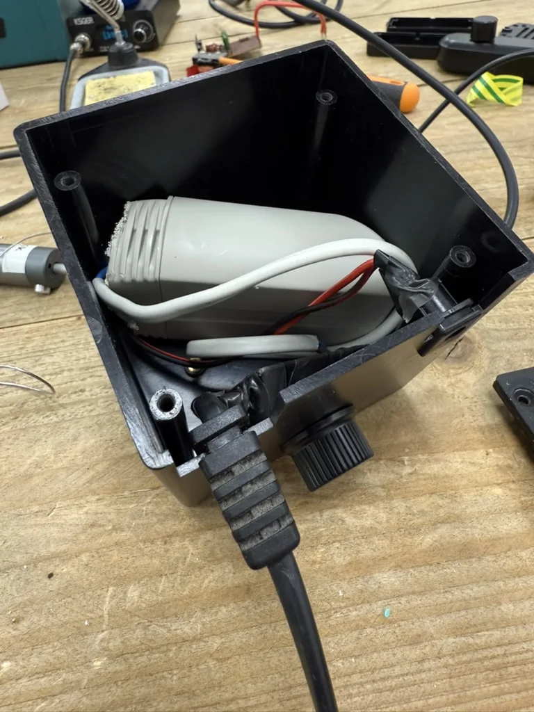
I fit the two devices inside the housing of the old transformer. I had to remove some plastic from the adapter housing. The fit was tight, but it worked out fine.
Now osqar can shine again.
Unfortunately I couldn’t restore the original electronics. But there are some benefits to a refresh: The 12V adapter is more efficient than the old power supply, and the dimmer makes sure that lowering the light intensity actually saves some energy. Also the dimmer setting used to have only high and low intensity and now became continuously adjustable.